How to set up a Harrier IP camera
This tutorial video will help you to quickly get started with your Harrier IP camera. Learn what you need for the set-up, how it works and how to control the camera.
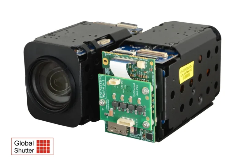
The Harrier 30x AF-Zoom IP Camera GS offers real-time full HD video output and a powerful Day & Night zoom lens with 30x optical zoom (32x digital zoom). A 3MP Sony global shutter CMOS sensor allows the capture of moving objects without the distortion that can occur with rolling shutters. The camera supports up to 1080p60 Full HD video output and the low-latency H.264 RTP streaming video is ideal for industrial and real-time applications.
The features include Day & Night mode (ICR functionality), 2D+3D Digital Noise Reduction and Defog Function, which make this global shutter block camera especially suitable for low-light scenarios and challenging environments. The camera also supports Digital Image Stabilization, Intelligent Motion Detection and Privacy Mask Function, as well as High/Back Light Compensation (HLC/BLC). External trigger and strobe out functions are available.
The IP Ethernet video stream is provided by the Harrier IP Camera Interface Board. The high-performance processor device on the camera interface board supports ONVIF services and a system administration website. This Harrier IP Website can be used to control the camera interface board, camera and the IP video output. Application examples of how to add text/graphical overlays to the live video stream and send VISCA commands to the camera via the ONVIF media service are available in the Harrier IP Example Software.
The Harrier IP Ethernet camera is available in two variants: regular Ethernet (AS-CIB-IP-001-30LGHD-A) and with Power over Ethernet (PoE, AS-CIB-IP-003-30LGHD-A). They can be easily evaluated using the Evaluation Kit for Harrier IP. Find a tutorial video on “How to set up a Harrier IP camera” under the Video tab.
As latency can be an issue in Ethernet IP imaging systems, Harrier IP camera hardware and firmware have been optimized to reduce latency to a minimum. Read more about how to obtain the lowest latency with your Ethernet IP autofocus-zoom camera and IP interface board system. For more details (and measured latencies for our Harrier IP AF-Zoom modules) please download the Technical Note: Obtaining the lowest latency from your Harrier AF-Zoom IP camera.
| Image sensor | 1/3.1-type Sony IMX900-AQR-C CMOS sensor, Pregius S (global shutter) |
||||||||||||
| Total no. of pixels | Approx. 3.280,000 pixels |
||||||||||||
| Effective no. of pixels | Approx. 3.200,000 pixels |
||||||||||||
| Shutter Type: | Global shutter |
||||||||||||
| Sync. System | Internal |
||||||||||||
| Video format (HD) | Camera: 1080p/60/50/30/25 fps, 720p/60/50/30/25 fps Interface board: 1080p 30fps |
||||||||||||
| Analog resolution | CVBS from camera |
||||||||||||
| Minimum illumination | Color(1/30s, 48dB) : 0.1 lux, BW(1/30s, 48dB) : 0.01 lux |
||||||||||||
| S/N ratio | Signal-to-Noise Ratio more than 50dB (AGC off) |
||||||||||||
| Lens (wide to tele) | 30x Day & Night Zoom Lens |
||||||||||||
| Viewing angle (FOV) |
|
||||||||||||
| Control protocol | ONVIF profile S (via interface board), VISCA (via ONVIF DeviceIO service) |
||||||||||||
| Baud rate | 2400 / 4800 / 99600 / 19200 / 38400 / 115200 bps |
| Trigger mode | Free run / Ext-trigger |
| Trigger polarity | Active Low / Active High |
| Trigger delay | 0 ~ 255.9ms |
| Strobe polarity | Active Low / Active High |
| Strobe delay | Ext-Trigger: 0 ~ 255.9ms / Free run: 0 ~ (1V period – Width)ms |
| Strobe width | Ext-Trigger: 0 ~ 255.9ms / Free run: 0 ~ (1V period – Delay)ms |
| Functions Ext-trigger | Shutter Speed: 1/30(25) ~ 1/40,000 sec |
| Focus Mode | Auto / One Push / Manual |
| Distance (m) | 0.5 / 1.5 / 3.0 / 5.0 / 10.0 m |
| Zoom Speed | 0 (Slow) ~ 7 (Fast) |
| Lens Refresh | One Push / 1day ~ 10days |
| E.Zoom | Off / MAX 2x ~ 32x |
| Zoom Preset | 5 preset |
| Exposure Mode | Auto / Iris. Priority / Shut. Priority / Manual |
| AGC (Automatic gain control) | 0 ~ 10 steps |
| Shutter speed | 1/30(25) ~ 1/40,000 sec |
| Iris | Close ~ F1.6 |
| DSS (Digital Slow Shutter) | Off / 2x / 4x / 8x / 16x / 32x (/64x: 60 or 50fps mode only) |
| Flickerless | Off / On / Auto |
| Brightness | 0 ~ 14 steps |
| High/Back Light Compensation (HLC/BLC) | Off / BLC / HLC |
| Day & Night | Auto / Day / Night / Ext-in |
| Night Function Set | Off / On |
| White Balance Mode | Auto / One Push / Manual / Indoor / Outdoor / Auto-Extended |
| White Balance | Red Gain: 0 ~ 100 steps (Manual mode only) |
| Digital Noise Reduction (DNR) | 2D/3D, 2D+3D (Level : 0 ~ 15 steps) |
| Mirror | Off / H / V / H&V |
| Sharpness | 0 ~ 15 steps |
| Contrast | 0 ~ 20 steps |
| Image Bright | 0 ~ 20 steps |
| DWDR | Off / Manual / Auto [Digital Wide Dynamic Range] |
| Defog | Off / Manual / Auto |
| Freeze | Off / On |
| Gamma | 0.35 ~ 0.70 |
| Privacy mask | Off / On (8 points) |
| Motion detection | Off / On (3 points) |
| Digital Image Stabilization (DIS) | Off / On |
| Defect detection | Off / On |
| Video input (J8) | The Harrier IP Camera Interface Board is connected to the main camera module by a 100mm KEL cable. The corresponding connector on the camera interface board is the same 30-way miniature connector that carries camera LVDS video signals. |
| Video resolution/rate | 1080p 30 fps |
| Video compression | H.264 |
| SD card (J5/J6) | The Harrier IP Camera Interface Board is fitted with a standard micro-SD socket (J5) that can accept cards of up to 512GB. There is also a 12-way 0.5mm pitch FFC connector (J6) to enable connection to external/remote SD card sockets. |
| Camera control | ONVIF profile S, VISCA (via Ethernet connection and ONVIF DeviceIO service) |
| Protocol support | ONVIF Profile S, IPv4/v6, HTTP, HTTPS, RTSP, RTP, TCP, UDP, RTCP, ICMP, DHCP |
| PELCO/microphone connector (J7) | The Harrier IP Camera Interface Board is fitted with a 10-way 0.8mm pitch connector to enable connection to a PELCO controller and mono microphone. |
| USB (J3) | The Harrier IP Camera Interface Board is fitted with a 12-way 0.5mm pitch FFC connector (J3) to enable connection to external/remote SD card sockets. |
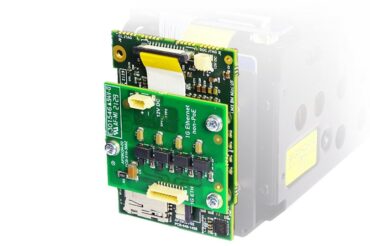
| Board Options | A Harrier IP interface solution typically comprises two boards – a SoC processing board (AS-CIP-IP-SOC-001-A) and an Ethernet connection board (AS-CIP-IP-IFETH-001-A). An FFC cable connects these two boards and they can be mounted directly onto a block camera or stacked on top of each other. The boards are available separately, as a set or mounted on a camera (see product image). There are two versions of the connection board: the Ethernet connection board (AS-CIP-IP-IFETH-001-A) and a Power over Ethernet-enabled version (AS-CIP-IP-IFPOE-001-A). Specifications of the Ethernet or PoE connection board are found in the datasheets available for both boards (see download tab). |
| Operation | When connected to a suitable power supply, the Harrier IP Camera Interface Board will boot and then power up the camera. Once the camera has initialized, it will start transmitting an LVDS video stream; the camera interface board will compress the video (H.264), convert it to RTP format, and broadcast it from the Ethernet port. Any RTP/ONVIF compatible application (e.g. VLC player or GStreamer) can then receive and display the video. ONVIF services can be used to control the camera and video stream settings. |
| Setting an IP address | By default, the Harrier IP Camera Interface Board is automatically assigned an IP address using DHCP, but it can be set to a fixed IP address using the Harrier IP Website or the ONVIF Device Management Service. When setting fixed IP addresses, please ensure that the address is correct and that you make a record of the new address before making the changes, as it can be very difficult to locate a device at an unknown/incorrect IP address. |
| ONVIF and RTSP Services | The Harrier IP Camera Interface Board platform supports an RTSP server for streaming video and the ONVIF profile S standard for camera control. The RTSP server enables connected host devices to receive and control the H.264 video stream. ONVIF is a SOAP webservice that standardises the network interface for network video products. The ONVIF services include the following areas:
The ONVIF and RTSP services can be consumed from many programming languages and several software frameworks already exist to use those services.
Visual Studio can load the WSDL files that describe the various ONVIF SOAP services and generate a C#class with methods for the various ONVIF functions. The ONVIF services supported are listed below:
For detailed information on these services please refer to the ONVIF documentation at https://www.onvif.org/profiles/specifications/. |
| Encoding Interval – Low Latency 1080p30 | The Harrier IP Camera Interface Board can be configured to receive a low latency 60Hz video and convert it to a 30Hz video, reducing the latency, network bandwidth and recording space required. |
| Harrier IP Website | The Harrier IP Camera Interface Board hosts a website that can be used to control the board and camera. When the board is connected, the website can be accessed by entering the IP address of the camera into a web browser. For more information, see the Harrier IP Camera Interface Board datasheet (download tab). |
| Block Camera Control Over Ethernet | The camera video mode and H.264 compression parameters can be managed using the ONVIF media service. The ONVIF Imaging service enables any ONVIF-compliant third-party software/application to control the camera settings. However, most AF-zoom block cameras have many more settings than those available through the ONVIF Imaging service. These additional settings are usually managed using VISCA commands sent over a serial interface. The Harrier IP Camera Interface Board supports direct serial communication with cameras; applications can access this serial interface via the ONVIF DeviceIO service. |
| RS-485 Interface Control Over Ethernet | The Harrier IP Camera Interface Board supports direct RS-485 serial communication with external devices. Applications can access the serial port via the ONVIF DeviceIO service.
Function SendReceiveSerialCommand() is used to send and receive data to the port. |
| RS-485 VISCA Service for Camera Control | The RS-485 VISCA service enables direct control/VISCA communication with the block camera from an external host attached to the RS-485 port of the Harrier IP board. The RS-485 VISCA service runs at start-up; when connected it receives data from the RS-485 port and will forward valid VISCA messages to the block camera (VISCA address 0x81), or to the Harrier IP board (VISCA address 0x82). When running, the RS-485 VISCA service has full ownership of the RS-485 port; this means that other services (e.g. ONVIF DeviceIO calls) cannot use the RS-485 port while the service is active. For more information, please consult the datasheet (download tab) of the Harrier IP Camera Interface Board. |
| Video Graphical Overlay Control | The Harrier IP Camera Interface Board is able to superimpose graphics and text on the live video stream. This includes graphics with transparent/alpha blended pixels. The application manages these overlays using an API from the ONVIF Media service. The overlays can be stored in system memory (volatile) or in the flash on the platform (non-volatile). The flash has a high but limited number of guaranteed writes, hence in applications where the overlays are frequently changed it is recommended that the volatile setting be used. The functions CreateOSD() and SetOSD() of the media profile have had an optional boolean element added to select if the OSD should be volatile (saved to memory) or not (saved to flash). More in the Harrier IP Camera Interface Board datasheet (download tab). |
| SD Card Interface | The SD card interface supports all standard micro SD cards (up to 512GB) and operates them in SDR25 mode. High data rates that come with UHS II cards are not supported and UHS II cards will operate in UHS I modes (lower data rate). The SD card can be used to store graphical overlays or video from the camera. |
| Harrier IP Example Software | The Harrier IP Example Software from Active Silicon contains sample application code that shows how to use the ONVIF services for adding text and graphical overlays to the live video stream and sending VISCA commands (over IP) to the camera to enable full camera control. |
| Status LED ("LED1/2/3/4") | The Harrier IP Camera Interface Board is fitted with several multi-color LEDs to indicate camera status.
|
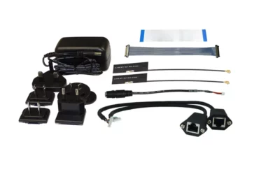
| Evaluation Kit | An Evaluation Kit for Harrier IP is available. This kit enables fast and effective evaluation and testing of the Harrier IP Camera Interface Board and cameras based on this interface board. |
| Ethernet support | On board magnetics for 10/100/1G Ethernet support |
| Versions | The board is available in two versions, the Harrier Ethernet Connection Board (AS-CIB-IP-IFETH-001-A) and the Harrier PoE Connection Board (AS-CIB-IP-IFPOE-001-A); the latter allowing Power over Ethernet. |
| Connection to Harrier IP Camera Interface Board | The Ethernet connection board connects to the Harrier IP Camera Interface Board via a 24-way FFC/FPC that also carries power to the Harrier IP Camera Interface Board (and any camera connected to it). |
| Mounting of the Ethernet connection board | The Ethernet/PoE connection board can be mounted on the back of a camera, or stacked on top of the Harrier IP Camera Interface Board. See product image and views of the boards mounted in the Harrier IP Camera Interface Board datasheet (download tab). |
| PoE power delivery | On the Harrier PoE Connection Board (AS-CIB-IP-IFPOE-001-A) the PoE power delivery board is an isolated, regulated, DC-DC converter with an output of 12V, an input range of 37-57V DC, a typical efficiency of 84% and full 2250 Volt DC isolation. The board is PoE class 0 IEEE 802.3af compliant powered device with input undervoltage lockout and output current limit. To guarantee optimal heat dissipation, a heatsink is attached to the Harrier PoE Connection Board. |
| Power requirement | 9 – 15V DC |
| Power consumption | TBA |
| Operating temperature | 0°C to +50°C |
| Storage temperature | -20°C to +60°C |
| Operating humidity | 20% to 80% (no condensation) |
| Dimensions (L x W x H) | AS-CIB-IP-001-30LGHD-A: 111 x 50 x 65.5 (L x W x H) AS-CIB-IP-003-30LGHD-A: 123 x 50 x 65.5 (L x W x H) |
| Weight | ca. 321g (AS-CIB-IP-001-30LGHD-A) |
| Download | File Type | File Size | |
|---|---|---|---|
Datasheets |
Datasheet Harrier 30x AF-Zoom Camera Global Shutter | 824.49 KB | |
| Product overview - Harrier IP | 435.55 KB | ||
| Datasheet Harrier IP Camera Interface Board | 978.89 KB | ||
| Datasheet Harrier Ethernet Connection Board (for AS-CIB-IP-001-36LGHD-A) | 481.66 KB | ||
| Datasheet Harrier PoE Connection Board (for AS-CIB-IP-003-36LGHD-A) | 561.69 KB | ||
Manuals & Quick Start Guides |
Technical Reference Manual - Harrier 30x AF-Zoom Camera v1.02 | 6.20 MB | |
Software |
HarrierControl Camera Software v.1.4.2 | zip | 15.21 MB |
CAD Drawings & Data |
Dimensions Harrier 30x AF-Zoom Camera GS | webp | 107.28 KB |
Other Downloads |
Tech Note TN015: Obtaining the lowest latency from your Harrier IP camera v2.06 | 496.13 KB | |
| Brochure - Cameras for drones, UAVs and gimbals | 1.41 MB |
| Part number | Description |
|---|---|
| AS-CIB-IP-001-30LGHD-A |
Harrier 30x AF-Zoom IP Camera with global shutter sensor. Assembled camera system: camera with interface boards (AS-CIB-IP-SOC-001-A and AS-CIB-IP-IFETH-001-A) mounted on the camera and with connecting cables fitted. |
| AS-CIB-IP-003-30LGHD-A |
Harrier 30x AF-Zoom IP Camera with global shutter sensor. Assembled camera system: camera with interface boards (AS-CIB-IP-SOC-001-A and AS-CIB-IP-IFPOE-001-A [PoE]) mounted on the camera and with connecting cables fitted. |
| AS-CAM-30LGHD-A |
Harrier 30x AF-Zoom Camera with global shutter sensor (LVDS). |
| AS-CIB-IP-001-A |
Harrier IP Camera Interface Board system. |
| AS-CIB-IP-003-A |
Harrier IP Camera Interface Board system; Power over Ethernet. |
| AS-CIB-BRK-007-A |
Metal bracket, screws and spacers for mounting the AS-CIB-IP-SOC-001-A to a Harrier 30x AF-Zoom Camera GS. |
| AS-CIB-IP-001-EVAL-A |
Evaluation kit for the Harrier IP for evaluating the Harrier IP Camera Interface Board and IP cameras based on that board. Contains a power supply, a power adapter cable (AS-CBL-549-503Y), a 30-way micro coax KEL cable (AS-CIB-USL30-100MM, for connecting a camera to the camera interface board), and Ethernet adapter cables (AS-CBL-935-153S for non-PoE boards/cameras and AS-CBL-020-731U for PoE boards/cameras). Does not include boards or a camera. |
| AS-CBL-935-153S |
Ethernet interface adapter cable, JST to RJ45 socket |
| AS-CBL-020-731U |
Ethernet interface adapter cable, Molex to RJ45 socket – for use with PoE enabled products |
| AS-CBL-549-503Y |
Power adapter cable, barrel socket to 4-way JST connector |
| AS-CIB-USL30-100MM |
30-way micro-coax cable for connecting the interface board to the camera. Length 100mm (Manufacturer: KEL, part number: USL20-30SS-005-C). |
This tutorial video will help you to quickly get started with your Harrier IP camera. Learn what you need for the set-up, how it works and how to control the camera.
Active Silicon offers a range of block cameras that provide image transmission and capture in a variety of outputs including 3G-SDI/HD-SDI, USB3, HDMI, and Ethernet H.264 IP. Watch this video to learn more about Harrier AF-Zoom cameras.