Harrier 10x AF-Zoom IP Camera (MP1010M / MP1110M)
Part Number: AS-CIB-IP-00x-1110-A and AS-CIB-IP-00x-1010-A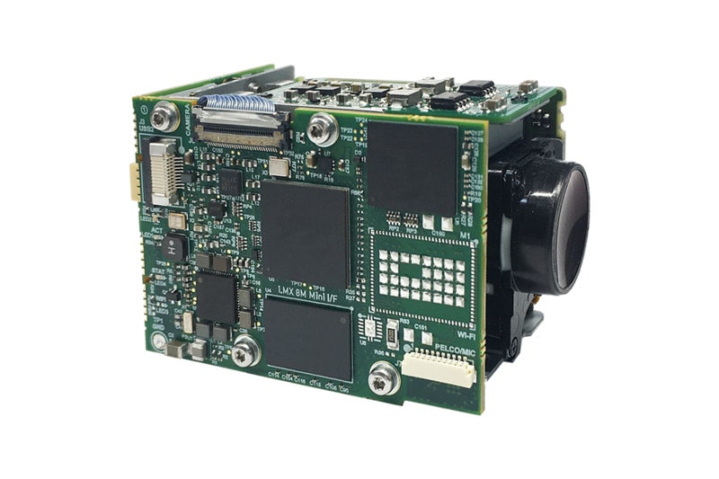
Features
- IP (Ethernet) block camera solution based on Tamron MP1010M/MP1110M.
- Low latency H.264 RTP streaming video.
- Lightweight and compact 4 Megapixel camera.
- 10x optical zoom, 16x digital zoom.
- 1/3″ CMOS progressive scan image sensor.
- Supports all HD modes up to 1080p60/30 (MP1110M/MP1010M).
- Built-in web server for setup and configuration.
- Options for Ethernet, PoE and wireless interfaces.
The Tamron MP1010M or MP1110M cameras are end-of-life. Please contact sales for remaining stock and alternative products. We recommend the Harrier 10x AF-Zoom IP Camera (Tamron MP3010M-EV) as their improved successor. Lighter and with similar dimensions, it is the smallest AF-Zoom camera on the market.
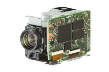
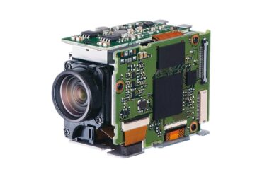
The Harrier 10x AF-Zoom IP Camera (Tamron MP1010M/MP1110M) comes with an 10x optical zoom and provides IP (Ethernet) video output with low latency H.264 RTP streaming. Based on the Tamron MP1010M, this Ethernet IP autofocus-zoom camera is available with optical vibration compensation (-VC version), or without (-WP version).
This OEM camera solution is extremely compact, measuring only 69.4 x 37.6 x 41.5mm and weighing only 105g. It is a high image-quality camera module with SMPTE 274M and SMPTE 296M compliant video output up to 1080p30 Full HD. Benefiting from Tamron’s high quality optical design and low reflection coating technologies, the camera offers color blur reduction, high contrast and many other sophisticated camera features.
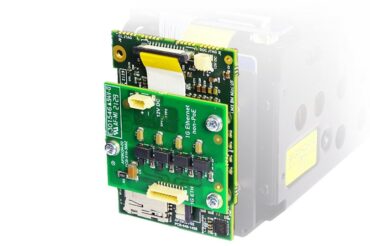
The IP Ethernet video stream is provided by the Harrier IP Camera Interface Board. The high-performance processor device on the Harrier IP Camera Interface Board supports ONVIF services and a system administration website. This Harrier IP Website can be used to control the camera interface board, camera and the IP video output. Application examples of how to add text/graphical overlays to the live video stream and send VISCA commands to the camera via the ONVIF media service are available in the Harrier IP Example Software.
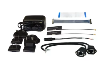
The Harrier IP Ethernet camera is available in four variants: regular Ethernet (AS-CIB-IP-001-1010-A), wireless version (AS-CIB-IP-002-1010-A), Power over Ethernet (PoE, AS-CIB-IP-003-1010-A) and wireless PoE (AS-CIB-IP-004-1010-A). It can be easily evaluated using the Evaluation Kit for Harrier IP. Find a tutorial video on “How to set up a Harrier IP camera” under the Video tab.
As latency can be an issue in Ethernet IP imaging systems, Harrier IP camera hardware and firmware has been optimized to reduce latency to a minimum. Read more about how to obtain the lowest latency with your Ethernet IP autofocus-zoom camera and IP interface board system. For more details (and measured latencies for our Harrier IP AF-Zoom modules) please download the Technical Note: Obtaining the lowest latency from your Harrier AF-Zoom IP camera.
Camera specifications
| Image sensor | 1/3″ CMOS (progressive scan) |
| Effective no. of pixels | Approx. 4,080,000 pixels |
| Pixel output (H x V) | 1920 x 1080; 1280 x 720 |
| Video format (HD) | 1080p/30, 1080p/25, 1080i/60, 1080i/50, 720p/60, 720p/50,720p/30, 720p/25, 1080p/60 (MP1110M only), 1080p/50 (MP1110M only) |
| Minimum illumination | 0.5lx (1/30 sec, F1.8, 50%) |
| Recommended illumination | 100lx to 100,000lx |
| S/N ratio | More than 50dB |
| Gain | Auto / manual |
| Shutter speed | 1/1 to 1/10,000 sec |
| Sync system | Internal |
| Exposure compensation | -12dB to +12dB (total 13 steps) |
| Backlight compensation | ON / OFF |
| Gamma | Standard / straight |
| Aperture control | 16 steps |
| White balance | ATW1 (narrow), ATW2 (wide), one push, manual (B, R) |
| AE (Auto exposure mode) | Auto, manual, priority mode (shutter / iris) |
| Lens (wide to tele) | 10x optical zoom f=3.3 to 33.0mm F1.8 to 3.4 |
| Zoom mode | Standard / variable / direct |
| Zoom movement speed (wide to tele) | 1.4 sec (focus tracking ON) |
| Digital zoom | Up to 16x |
| Focusing system | Auto, manual, one push, AF sensitivity |
| Horizontal viewing angle (wide to tele) | 58.2° to 6.9° (Tamron MP1010M) |
| Minimum object distance (wide to tele) | 10mm to 800mm |
Camera functions
| VC (Vibration Compensation) | Available |
| Wide-D | Available |
| Defog | Available |
| Noise reduction (3D + 2D) | Available |
| Digital output | Available |
| Privacy zone masking | Available |
| Slow shutter | Available |
| Picture effects (black white) | Available |
| Picture freeze | Available |
| Electronic flip (e-flip) | Available |
| Mirror image | Available |
| Title display | Available |
| Test pattern | Available |
| Crosshairs | Available |
Specifications - Harrier IP Camera Interface Board
| Video input (J8) | The Harrier IP Camera Interface Board is connected to the main camera module by a 100mm KEL cable. The corresponding connector on the camera interface board is the same 30-way miniature connector that carries camera LVDS video signals. |
| Video resolution/rate | 1080p 30fps |
| Video compression | H.264 |
| SD card (J5/6) | The Harrier IP Camera Interface Board is fitted with a standard micro-SD socket (J5) that can accept cards of up to 512GB. There is also a 12-way 0.5mm pitch FFC connector (J6) to enable connection to external/remote SD card sockets. |
| Camera control | ONVIF profile S compatible, VISCA (via Ethernet connection and ONVIF DeviceIO service) |
| Protocol support | ONVIF Profile S, IPv4/v6, HTTP, HTTPS, RTSP, RTP, TCP, UDP, RTCP, ICMP, DHCP |
| Wireless Protocols | 802.11 a b g n and ac |
| PELCO/microphone connector (J7) | The Harrier IP Camera Interface Board is fitted with a 10-way 0.8mm pitch connector to enable connection to a PELCO controller and mono microphone. |
| USB (J3) | The Harrier IP Camera Interface Board is fitted with a 12-way 0.5mm pitch FFC connector (J3) to enable connection to external/remote SD card sockets. |
Specifications - Harrier Ethernet Connection Board
| Harrier Ethernet/IP board connector (J1) | The Harrier Ethernet Connection Board is fitted with a 4-way JST connector (J3) for connection to an external power supply. The same supply will also power the Harrier IP Camera Interface Board via J1. |
| Ethernet connector (J2) | The Harrier Ethernet Connection Board is fitted with a 9-way JST connector (J2) for connection to an external 10/100/1000M Ethernet connection/cable. |
| Power connector (J3) | The Harrier Ethernet Connection Board is fitted with a 4-way JST connector (J3) for connection to an external power supply. The same supply will also power the Harrier IP Camera Interface Board via J1. |
Operation and features - Harrier IP Camera Interface Board
| Operation | When connected to a suitable power supply the Harrier IP Camera Interface Board will boot and then power-up the camera. Once the camera has initialized it will start transmitting an LVDS video stream; the camera interface board will compress the video (H.264), convert it to RTP format, and broadcast it from the Ethernet port. Any RTP/ONVIF compatible application (e.g. VLC player or GStreamer) can then receive and display the video. ONVIF services can be used to control the camera and video stream settings. |
| Setting an IP address | By default, the Harrier IP Camera Interface Board is automatically assigned an IP address using DHCP, but a fixed IP address can be set using the Harrier IP Website or the ONVIF Device Management Service. |
| ONVIF Services | The Harrier IP Camera Interface Board platform is controlled using the ONVIF protocol and implements the ONVIF Profile S. Visual Studio can load the WSDL files that describe the various ONVIF SOAP services and generate a C# class with methods for the various ONVIF functions.
For detailed information on these services please see the ONVIF documentation at https://www.onvif.org/profiles/specifications/; examples of how to use the media and DeviceIO services are available from Active Silicon. |
| Camera control | The camera video mode and H.264 compression parameters can be managed using the ONVIF media service. The ONVIF Imaging service enables any ONVIF-compliant third-party software/application to control the camera settings. However, most AF-zoom block cameras have many more settings than those available through the ONVIF Imaging service. These additional settings are usually changed using VISCA commands sent over a serial interface. The Harrier IP Camera Interface Board supports direct serial communication with cameras and applications can access this serial interface via the ONVIF DeviceIO service: function SendReceiveSerialCommand(). This function allows applications to send, and optionally receive, data to/from the camera. Please refer to the ONVIF DeviceIO specification for the complete documentation of this function. This means that all camera features supported by the VISCA protocol can be controlled by the end application over the Ethernet interface. For examples, please refer to the Harrier IP Example Software. For more information on VISCA control and camera features, please refer to the documentation for your camera. |
| Harrier IP Website | The Harrier IP Camera Interface Board hosts a website which can be used to control the board and camera. |
| Video Graphical Overlay Control | The Harrier IP Camera Interface Board is able to superimpose graphics and text on the live video stream. This includes graphics with transparent/alpha blended pixels. The application manages these overlays using an API from the ONVIF Media service. The overlays can be stored in system memory (volatile) or in the flash on the platform (non-volatile). The flash has a high but limited number of guaranteed writes, hence in applications where the overlays are frequently changed it is recommended that the volatile setting be used. The functions CreateOSD() and SetOSD() of the media profile have had an optional boolean element added to select if the OSD should be volatile (saved to memory) or not (saved to flash). More in the Harrier IP Camera Interface Board datasheet (download tab). |
| SD Card Interface | The SD card interface supports all standard micro SD cards (up to 512GB) and operates them in SDR25 mode. High data rates that come with UHS II cards are not supported and UHS II cards will operate in UHS I modes (lower data rate). The SD card can be used to store graphical overlays or video from the camera. |
| Harrier IP Example Software | The Harrier IP Example Software from Active Silicon contains sample application code that shows how to use the ONVIF services for adding text and graphical overlays to the live video stream and sending VISCA commands to the camera to enable full camera control. |
| Status LED ("LED1/2/3/4") | The Harrier IP Camera Interface Board is fitted with several multi-color LEDs to indicate camera status.
|
| Evaluation Kit | An Evaluation Kit for Harrier IP is available. This kit enables fast and effective evaluation and testing of the Harrier IP Camera Interface Board and cameras based on this interface board. |
Physical and environmental details
| Power requirement | 8.25V to 12.25V DC |
| Power consumption | 5W typical (4.5 – 6W peak, depending on lens operation and video mode, does not include WiFi operation) |
| Operating temperature | 0°C to +60°C (ambient environment). |
| Storage temperature | -20°C to +60°C. |
| Operating humidity | 20% to 80% (no condensation) |
| Dimensions (L x W x H) | 69.4 x 37.6 x 41.5mm (L x W x H) |
| Weight | 125g |
| Download | File Type | File Size | |
|---|---|---|---|
Datasheets |
Datasheet Tamron MP1010M camera | 169.77 KB | |
| Datasheet Tamron MP1110M camera | 101.88 KB | ||
| Datasheet Harrier IP Camera Interface Board | 978.89 KB | ||
| Datasheet Harrier Ethernet Connection Board | 481.66 KB | ||
| Datasheet Harrier PoE Connection Board | 561.69 KB | ||
Manuals & Quick Start Guides |
Tamron MP1010M-VC Technical Reference Manual v1.02 | N/A | N/A |
| Tamron MP1110M-VC Technical Reference Manual v1.06 | N/A | N/A | |
| Harrier IP CIB Quickstart Guide v2.5 | 1.19 MB | ||
Software |
Harrier IP Example Software v1.03 | zip | 653.93 KB |
CAD Drawings & Data |
3D CAD Model (zipped STEP file) - Harrier 10x AF-Zoom IP Camera (Tamron MP1010M) | zip | 16.59 MB |
| Mechanical Overview - Harrier 10x AF-Zoom IP Camera (Tamron MP1010M) | 588.52 KB | ||
| 3D CAD Model (zipped STEP file) - Harrier 10x AF-Zoom IP Camera (Tamron MP1010M) - with wireless option | zip | 16.65 MB | |
| Mechanical Overview - Harrier 10x AF-Zoom IP Camera (Tamron MP1010M) - with wireless option | 596.12 KB |
Related Products
Evaluation Kit for Harrier IP
Harrier IP Example Software
Harrier IP Camera Interface Board
Tamron MP1010M-VC (and -WP version)