Accessories & Cables
Evaluation Kit for Harrier SDI Cameras
Part Number: AS-CAM-SDI-EVAL-A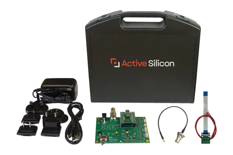
Features
- For evaluation of Harrier 10x and Harrier 36x AF-Zoom SDI Cameras.
- Includes the Harrier Evaluation Board, power supply and all cables required for fast setup.
- Immediate connection to 3G/HD-SDI and EX-SDI video outputs.
- VISCA™ camera control over USB COM port.
The Evaluation Kit for Harrier SDI Cameras delivers everything you need for rapid evaluation of the Harrier 10x and the Harrier 36x AF-Zoom SDI Cameras. The Evaluation Kit contains the Harrier Evaluation Board, a multi-region power adapter and a complete set of cables that enables you to quickly and easily setup and test Harrier SDI cameras.
The Harrier Evaluation Board provides power, VISCA serial communication to the camera and easy access to analog video output. For more information please download the Quickstart guide relevant for your camera (see Downloads).
Note: the Evaluation Kit does not include the camera.
SDI Camera Evaluation Kit
| AS-CAM-SDI-EVAL-A kit contents: |
Please note: Camera not included. |
| Weight of the evaluation kit: | 1.25 kg (including case) |
| Dimensions of the case: | 355mm x 310mm (max) x 90mm (L x H x D) |
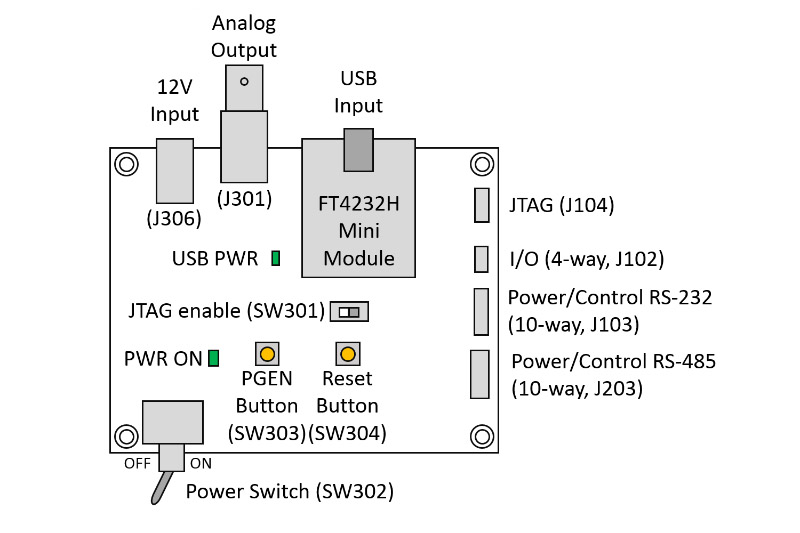
Harrier Evaluation Board Features
| Analog output (J301) | BNC connector to supply the analog video output that is supplied (when enabled) from the PWR/CTRL connector(s) (J3) on the camera interface board. |
| PGEN button (SW303) | Button, when pressed will activate the I/O signal (on J102) that causes the camera interface board to generate a test pattern video output. The test pattern will only be displayed whilst the button is being held down. |
| Reset button (SW304) | Button, when pressed it will activate the I/O signal (on J102) that causes the camera interface board to reset. Harrier AFZ cameras are not reset by this external signal; the CAM_Power VISCA command should be used to reset the camera. |
| Power (J306) | Power is supplied to the Harrier Evaluation Board from a 12V power supply via a barrel connector (J306). A connected camera and interface board are powered from the same supply via the Power Switch (SW302). When the Power Switch (and power supply) is switched ON the PWR ON LED will illuminate. The power supply is protected against reverse connection by a diode. |
| Serial communications/USB input | Serial camera/camera interface board control is provided by the USB interface (FTDi FT4232 Mini Module). A standard a USB Type A to mini USB Type B cable is used to connect the board to a PC. FTDI drivers are required to communicate with the FTDI module. These drivers are usually automatically installed on Windows 10. For Windows 7, it is recommended that the latest drivers are installed; these are available from here: The board USB connection will be seen by the PC software/OS as three standard virtual COM port connections. The number of each COM port is assigned by the software/OS being used. Windows Device Manager can be used to identify the three actual port numbers assigned. One of these will be the TTL serial interface to the camera. |
| Further information | The Harrier Evaluation Board datasheet, available in the download section, provides additional information on the board, including JTAG programming and firmware update, connector specifications of the board, test software, conformance and physical/environmental details. A photo and a diagram of the Harrier Evaluation Board can be viewed under the “other information” tab on this page as well as in the datasheet. |
| Download | File Type | File Size | |
|---|---|---|---|
Datasheets |
Datasheet Harrier Evaluation Board | 779.14 KB | |
Manuals & Quick Start Guides |
Harrier AF-Zoom SDI Cameras Quickstart Guide - v1.0.3 | 723.04 KB | |
Other Downloads |
List of available documentation | 180.38 KB |
| Part number | Description |
|---|---|
| AS-CAM-SDI-EVAL-A |
Evaluation Kit for Harrier 10x and Harrier 36x AF-Zoom SDI Cameras. Includes power supply, 9-way FFC breakout board (with 10-way wire cable), 9-way FFC cable, a MMCX-BNC adapter cable, a USB Type A to mini-USB Type B cable and the Harrier Evaluation Board with PC serial interface (via USB UART). |
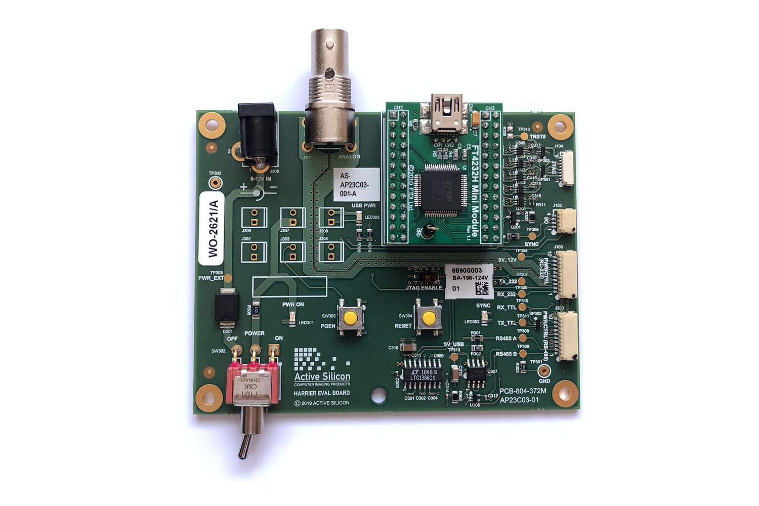
Harrier Evaluation Board
Related Products
View Product
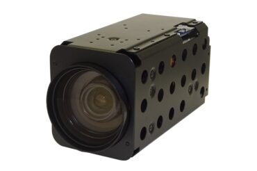
Harrier 10x AF-Zoom SDI Camera
View Product
View Product
Harrier 36x AF-Zoom SDI Camera with Global Shutter
View Product