Harrier Autofocus-Zoom Cameras
The Harrier HDMI Camera Interface Board is compatible with all our LVDS output cameras. Watch this video to learn more about Harrier AF-Zoom cameras:
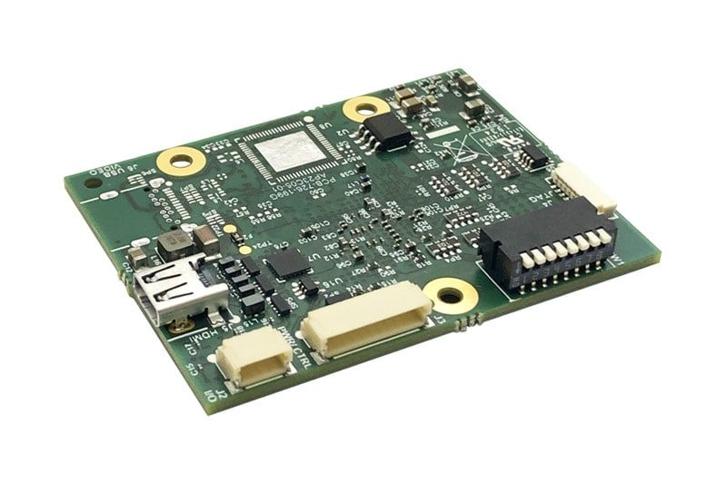
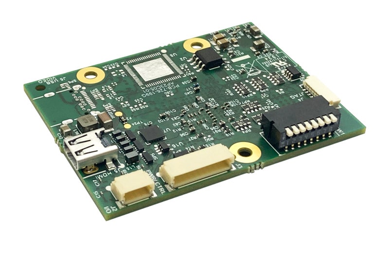
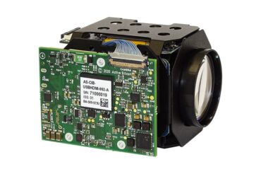
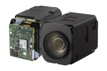
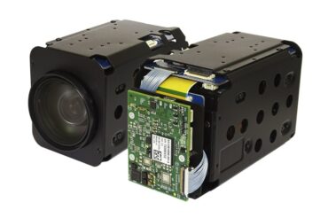
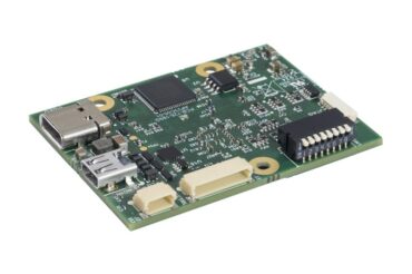
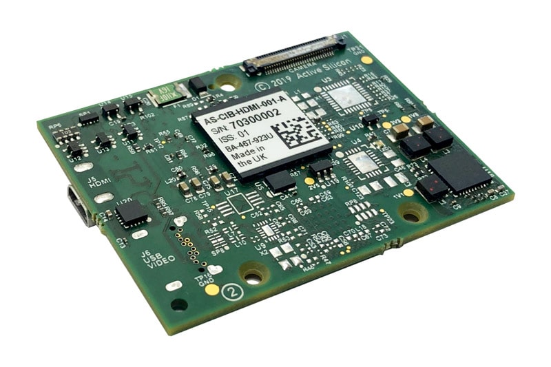
The Harrier HDMI Camera Interface Board (AS-CIB-HDMI-001-A) is a member of Active Silicon’s Harrier series of camera interface boards; it provides HDMI output for autofocus-zoom cameras such as the Tamron AF-Zoom cameras, the Sony EV-series cameras (e.g. Sony FCB-EV9520L), the Harrier 10x, 36x, 40x and 55x AF-Zoom Cameras.
The HDMI output is enabled when an HDMI cable is connected. On power-up, the camera video mode may be selected by the DIP switch settings on the board. Camera video modes, along with other camera and interface board functions, may also be controlled by TTL serial communication.
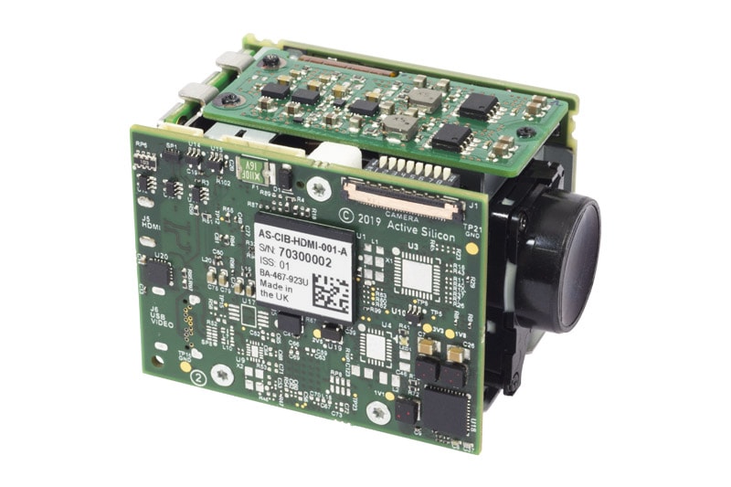
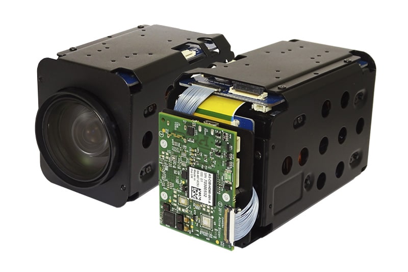
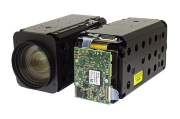
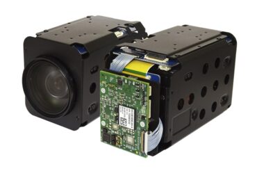
The Harrier HDMI Camera Interface Board can be purchased as board only or as assembled camera solution mounted to an autofocus-zoom camera. See our portfolio of HDMI output AF-zoom block cameras. The Harrier HDMI Camera Interface Board can also be supplied in a USB & HDMI variant.
Active Silicon also offer custom design services for camera interface boards and can adapt the product if it does not meet all your requirements. We are happy to discuss your system requirements and are looking forward to delivering the product you need.
For more information contact our team.
| HDMI Operation | The HDMI output is enabled when an HDMI cable is plugged in. The video mode of the HDMI output is the same as the output of the camera; there is no video mode conversion carried out in the interface board. To change the mode of the HDMI output the mode of the camera should be changed using VISCA serial commands or DIP switch settings (and power cycling). Video modes up to 1080p60 are supported. |
| Status LED | The interface board is fitted with a multi-color LED to indicate camera status. Solid Green: Solid Red: |
| Video Mode on Power-up | On power-up, the camera interface board will read the SW1 DIP switches and set the camera video mode accordingly. If the DIP switches are set for ‘Default Camera Mode’ then the camera (and camera interface board) will power-up in the video mode last set on the camera. For more information see the section on DIP switch settings in the datasheet. |
| Analog Output: | Some cameras can be set to output an analog video signal (e.g. Tamron MP1110M-VC), this signal is accessible as an output on the PWR/CTRL (J3) connector on the camera interface board. When the Tamron camera mode is set to PAL/NTSC (analog) output there is no digital video output from the camera and hence no HDMI output. |
| Test Pattern: | A video test pattern output may be selected by (a) driving pin 1 of connector J2 low, or (b) sending the appropriate VISCA command over serial communications. |
| Camera Control: | The camera settings (including video mode) can be controlled by serial VISCA commands (via the board PWR/CTRL connector – J3). For information on camera operation using VISCA serial commands please refer to the camera’s user/technical manual. |
| PWM Output: | A single 3.3V PWM output channel (J2) is enabled and controlled by interface board VISCA™ commands. Both the frequency and duty cycle of the PWM can be controlled. |
| CIB VISCA Commands: | For interface board operation using extended VISCA serial commands: The VISCA protocol can support connection of up to 8 cameras in a network; each camera is assigned a separate address. The default camera address is 1. To differentiate camera interface board specific commands from camera commands, the interface board is pre-assigned a fixed VISCA address of 2. For a list of the commands refer to the section Camera Interface Board VISCA Commands in the Harrier HDMI Camera Interface Board datasheet (download tab). Note: When listing VISCA commands a blank space is introduced between each byte to aid legibility. The numbers sent to the camera/interface board must be sent without blank spaces. |
| Mechanical Overview: | See “Other Information” tab above for mechanical overview diagrams. |
| KEL30 Connector (J1) | The interface board is fitted with a 30-way miniature connector to link to the matching connector on the camera. Connector type: KEL USL00-30L. Mating cable: KEL USL20-30SS-010-C (100mm length) or KEL USL20-30SS-005-C (50mm length) 30-way micro coaxial cable. This cable can be supplied with the interface board (see ordering information). Other lengths also available (subject to minimum order quantities). |
| Input/Output Connector (J2) | The interface board is fitted with an industry standard 4-way connector for Vsync/PWM signal output and test pattern/reset control inputs. Connector type: JST SM04B-SRSS-TB Mating cable: Suitable cable can be purchased as part of a cable kit (see order information tab). See datasheet (download tab) for pin assignments and control options. |
| Power and Control Connector (J3) | The interface board is fitted with an industry standard 10-way connector for power and serial control. Connector type: JST SM10B-SRSS-TB Mating cable: Suitable cable can be purchased as part of a cable kit (see order information tab). See datasheet (download tab) for pin assignment and output options. |
| JTAG Connector (J4): | Test connector used in manufacturing for circuit verification. |
| HDMI Output Connector (J5) | The interface board is fitted with a micro HDMI display output connector. HDMI output is active when an HDMI cable is connected. Connector type: HDMI Type D (micro). Mating Connector: Standard micro HDMI cable. |
| Video Mode DIP Switch (SW1) | The interface board is fitted with an 8-way DIP switch (SW1) to enable selection of camera video format on power-up. Switches 5-8 are reserved for future use. See datasheet (download tab) for the configuration of the DIP switch elements. |
| HDMI: | Compliant with HDMI specification 1.4a. |
| Approvals: | Active Silicon makes the following approval statements: CE RoHS3 REACH EMC
UL |
| Dimensions: | 51mm x 39mm. |
| Weight: | ~10g (interface board only, no cables). |
| Power Supply: | 8.25V to 15V. |
| Power Consumption: | 0.2-0.4W typical with HDMI active @1080p60. |
| Storage Temperature: | -40°C to +125°C. |
| Operating Temerature: | 0°C to +70°C (ambient environment). |
| Relative Humidity: | 10% to 90% non-condensing (operating and storage). |
| Download | File Type | File Size | |
|---|---|---|---|
Datasheets |
Datasheet Harrier HDMI Camera Interface Board | 802.84 KB | |
Manuals & Quick Start Guides |
Harrier HDMI CIB Quickstart Guide v1.6.2 | 814.58 KB | |
CAD Drawings & Data |
3D CAD Model (zipped STEP file) - Harrier HDMI Camera Interface Board | zip | 2.38 MB |
| Mechanical Overview - Harrier HDMI Camera Interface Board | 401.95 KB | ||
Other Downloads |
Technical Note - Troubleshooting guide for Harrier camera interface boards | 276.68 KB |
| Part number | Description |
|---|---|
| AS-CIB-HDMI-001-A |
Harrier HDMI Camera Interface Board. Board only, no cables included. |
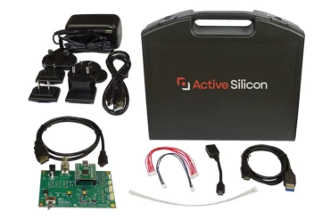
| AS-CIB-USBHDMI-001-EVAL-A |
Evaluation Kit for Harrier USB/HDMI, Harrier HDMI and all camera assemblies with these technologies. The kit includes power supply, board cables (AS-CIB-CBLKIT-003-A), micro-coax cable (AS-CIB-USL30-100MM, for connecting camera with camera interface board) and the Harrier Evaluation Board with PC serial interface (via USB UART). Not included: Camera and camera interface board. |
| AS-CIB-USL30-100MM |
30-way micro-coax cable for connecting the interface board (J1) to the camera. Length 100mm. |
| AS-CIB-USL30-50MM |
30-way micro-coax cable for connecting the interface board (J1) to the camera. Length 50mm. |
| AS-CIB-CBLKIT-003-A |
Cable kit for AS-CIB-HDMI-001-A containing cables for J2, J3, and J4 that connect to the Harrier Evaluation Board. |
| AS-CIB-FIXKIT-001-A |
Plastic clip, screws and spacers for mounting the AS-CIB-HDMI-001-A to Tamron MP1010 camera. |
| AS-CIB-BRK-007-A |
Metal bracket, screws and spacers for mounting AS-CIB-HDMI-001-A to Sony FCB-EV9520L or EV7520/A camera and Harrier 36x, 40x or 55x AF-Zoom Camera. |
| AS-CIB-BRK-009-A |
Metal bracket, screws and spacers for mounting AS-CIB-HDMI-001-A to Harrier 10x AF-Zoom Camera. |
The Harrier HDMI Camera Interface Board is compatible with all our LVDS output cameras. Watch this video to learn more about Harrier AF-Zoom cameras:
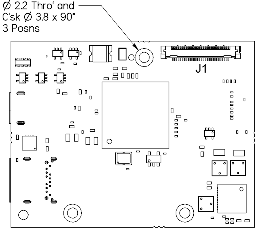
Note – when mounted on a camera, this side faces out/away from the camera.
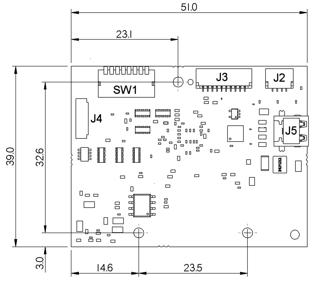
Note – when mounted on a camera, this side faces the camera.